In automated screwdriving production lines, pneumatic screw feeders deliver screws from the hopper to the tightening station, serving as the "first checkpoint" of the entire line. Once a jam occurs in the feeding process, downstream tightening stations are forced to stop, causing takt time losses and accelerated equipment wear from frequent start-stop cycles.
Statistics show that feeding system failures account for approximately 25%–35% of total downtime in automatic screwdriving equipment, with jamming being the most common and time-consuming fault type. Jamming manifests in various forms: screws stuck at track bends, piled up at the separation gate, blocked mid-way in the delivery tube, or failing to enter the blow nozzle due to incorrect orientation. Different symptoms often correspond to different root causes. Without a systematic troubleshooting approach, maintenance personnel can easily fall into a trial-and-error cycle of repeated disassembly and reassembly.
This article focuses on pneumatic screw feeders and categorizes ten typical causes of jamming across four dimensions—mechanical structure, screw material, process parameters, and environmental management. For each cause, we describe the symptom characteristics, inspection steps, and corrective measures. Finally, a priority-based systematic troubleshooting flow is provided for reference by field engineers.
I. Mechanical Structure (3 Causes)
1. Track Wear or Deformation
The track is the pathway for screws from the hopper to the delivery tube. After prolonged use, the track surface wears due to high-frequency friction from screws, especially at bends and step transitions. Wear increases the effective track width, causing screws to deviate or stack during sliding, eventually jamming at the widened section.
For inspection, use a standard gauge to measure the width at critical track sections. If it exceeds the design tolerance of ±0.1mm, the track should be replaced. During routine maintenance, inspect track wear every 500,000 fastening cycles and clean accumulated dust and oil from the track inner walls during model changeovers.
2. Pusher/Separation Mechanism Wear or Abnormal Clearance
Pneumatic screw feeders typically use air-cylinder-driven push plates or rotary separation disks to deliver individual screws to the blow position. The fit clearance between the push plate and track sidewall, as well as the positioning accuracy of the separation disk, directly determines whether the screw enters the blow nozzle in the correct orientation.
When the push plate edge chips, the separation disk locating pin wears, or the cylinder stroke drifts due to seal aging, screws may be pushed to incorrect positions, causing stacking or jamming at the separation gate. Inspection should focus on the push plate straightness, separation disk positioning repeatability, and cylinder stroke end-point stability. Worn parts should be replaced according to the manufacturer's maintenance schedule, not waiting for failures to occur.
3. Delivery Tube Bending, Crushing, or Loose Fittings (Pneumatic-Specific)
The delivery tube is the core component distinguishing pneumatic feeders from vacuum-type systems. Screws are propelled through the flexible tube by air pressure. If the tube is excessively bent during installation or maintenance, crushed by foot traffic, or if fittings loosen due to vibration, screws will collide, decelerate, or stop mid-flight inside the tube.
When inspecting the delivery tube, visually check along its entire length for sharp bends or crushed sections, and feel the tube wall for smoothness. Ensure fittings are securely fastened with clips or threads, and use cable ties if necessary. For long-distance feeding (over 2 meters), select smooth-walled PU hoses and add support brackets midway to prevent unsupported swinging.
II. Screw Material (3 Causes)
4. Mixed Specifications or Out-of-Tolerance Screws
If screws of different lengths, diameters, or head types are mixed in the same batch, the dimensional fit with the track and separation mechanism will be compromised. For example, overly long screws may jam at the track end step, while overly short screws may tip over at the separation gate.
The most direct inspection method is to compare the jammed screw with normal screws from the hopper, measuring overall length, shank diameter, head diameter, and head height. If tolerances exceed drawing requirements, contact the supplier to improve incoming consistency, and add length-detection or vision screening devices at the hopper entrance to prevent mixed material at the source.
5. Oil, Grease, or Foreign Matter on Screw Surfaces
During production, packaging, and transportation, screw surfaces may accumulate cutting fluid, rust-preventive oil, dust, or plastic debris. Oil reduces the friction coefficient between screw and track, causing screws to fly off the track at bends due to excessive inertia. Dust and debris accumulate in track gaps or separation clearances, gradually reducing effective passage space and eventually causing jamming.
Inspect jammed screws for shiny surfaces (oil presence) or visible particle adhesion. Solutions include requiring suppliers to provide cleaned screws, or adding upstream washing/drying stations. For contaminated batches, temporarily place oil-absorbent pads at the hopper bottom and shorten track cleaning cycles.
6. Mismatched Head Type and Track Profile
Different screw head types (pan head, countersunk head, round head, external hex, etc.) require different track profiles. Countersunk screws need a conical guide surface at the track bottom; if used with flat-bottom tracks designed for pan heads, the countersunk taper will interfere with the track bottom, causing orientation jamming.
During model changeover, verify compatibility between the screw head type and current track/separation tooling. If mismatched, replace with the appropriate track module or separation fixture. Post a head-type-to-tooling reference chart near the equipment to reduce changeover errors caused by human oversight.
III. Process Parameters (2 Causes)
7. Improper Vibratory Bowl Frequency or Amplitude
The vibratory bowl at the feeder inlet arranges screws from the hopper and delivers them to the track entrance. Frequency and amplitude directly determine screw conveying speed and orientation stability. Too low a frequency results in slow feeding that cannot match high-speed tightening takt time; too high a frequency causes violent screw bouncing inside the bowl, leading to stacking and orientation flipping before entering the track.
During troubleshooting, consult the manufacturer's recommended vibratory parameters for the screw specification (weight, length, head type), and fine-tune frequency and amplitude while observing screw arrangement at the track entrance. The ideal state is screws entering the track head-first, in stable orientation, with uniform spacing. Record optimal parameters as standard process documentation for that screw model.
8. Abnormal Blow Pressure or Airflow (Core Pneumatic Parameter)
Blow pressure is the direct driving force propelling screws through the delivery tube. Insufficient pressure prevents screws from reaching adequate initial velocity, causing mid-tube stalling. Excessive pressure increases screw impact energy against tube walls, potentially causing rebound, rotation, or jamming at bends. Insufficient airflow can also cause multiple screws to congest at the blow nozzle.
Connect a pressure gauge at the blow valve outlet to confirm pressure is within the manufacturer's recommended range (typically 0.4–0.6 MPa, depending on tube length and screw specification). Check for clogged air filters or air leaks in tubing. If line air pressure fluctuates significantly, install an independent pressure regulator upstream of the feeder to ensure stable pressure.
IV. Environment and Management (2 Causes)
9. Improper Hopper Level Management
When screw inventory in the hopper is too low, screw distribution density in the vibratory bowl decreases, preventing continuous stable feeding flow and causing "empty vibration" and intermittent material shortage. Excessive inventory increases pressure on bottom-layer screws, causing stacking and squeezing at the track entrance—especially with irregular head types or burr-covered surfaces.
The best practice is to install high/low level sensors in the hopper, triggering automatic alarms for low level and stopping refill at high level. During daily operation, maintain screw height between one-third and two-thirds of hopper capacity to ensure continuous feeding while avoiding excessive stacking.
10. Ambient Temperature and Humidity Affecting Screw Mobility
Ambient temperature and humidity significantly affect screw mobility. In high-humidity environments, metal screw surfaces may condense moisture, causing slight rusting or thickened oxide films that increase friction between screw and track. In low temperatures, lubricant viscosity increases, causing sluggish pusher mechanism motion and reduced separation accuracy.
For precision fastening lines, maintain the feeder area at 20–26°C with 45%–65% relative humidity. If line environment cannot be controlled, place desiccant packs in the hopper or select screws with anti-rust surface treatment. Before cold-weather startup, allow the equipment to run empty for five minutes to bring moving parts and lubrication systems to operating temperature.
V. Systematic Troubleshooting Flow and Priority Recommendations
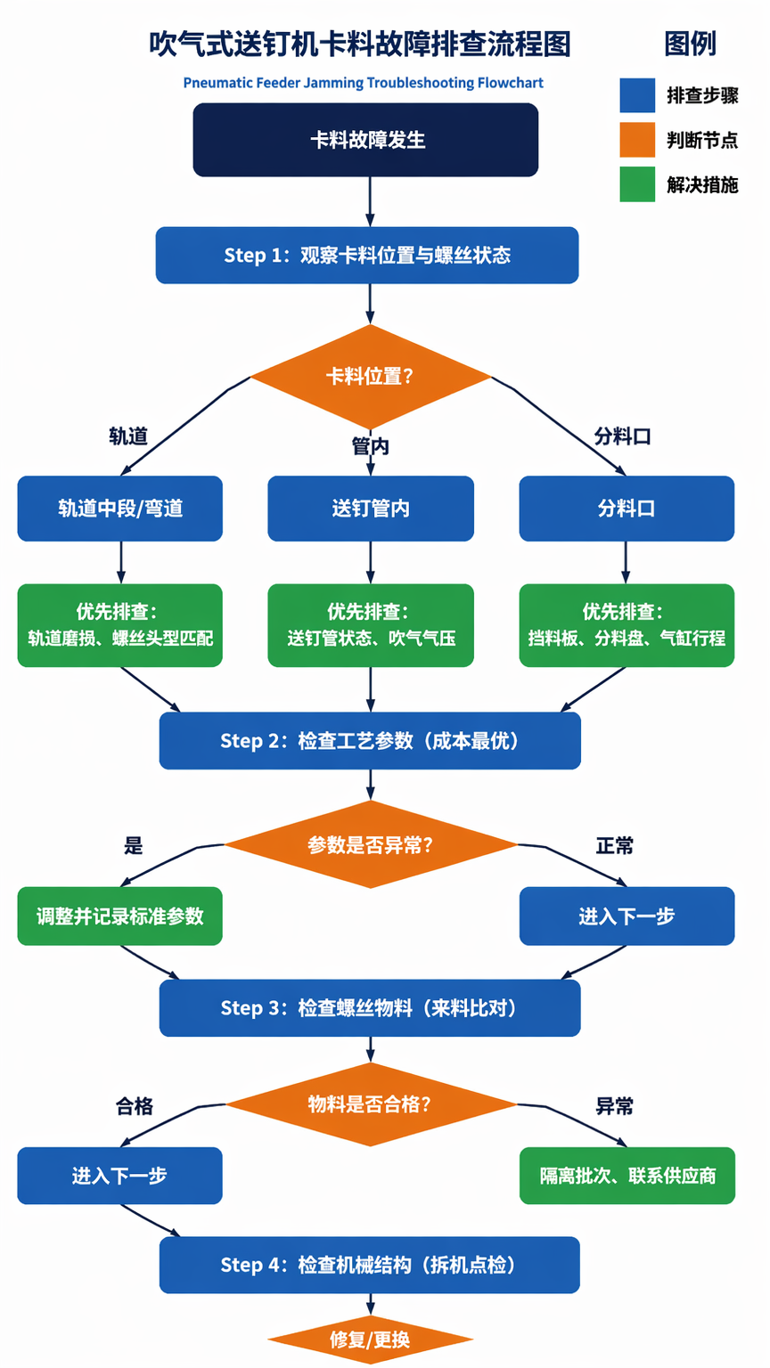
When facing jamming faults, maintenance personnel often want the "fastest" solution, but blind disassembly may introduce new problems. We recommend the following priority-based troubleshooting sequence:
Step 1: Observe jamming location and screw condition. Screws stuck mid-track suggest priority inspection of track wear and head-type matching; stuck in delivery tube suggests priority inspection of tube condition and pressure parameters; stuck at separation gate suggests priority inspection of pusher/separation mechanisms.
Step 2: Check process parameters. Among the ten causes, process parameter adjustments (vibration frequency, blow pressure) have the lowest cost and fastest effect. Before disassembling equipment, verify current parameters against standard process documentation and try fine-tuning to observe results.
Step 3: Check screw material. Compare jammed screws with standard samples to confirm specifications, surface condition, and head type. If incoming material is problematic, immediately quarantine the batch and contact the supplier.
Step 4: Check mechanical structure. If the first three steps do not resolve the issue, disassemble the track, pusher mechanism, and delivery tube to inspect wear, deformation, and looseness, replacing or repairing as needed.
Step 5: Evaluate environmental factors. Check temperature, humidity, and hopper level as indirect factors, optimizing on-site management. Record each jam's location, time, cause, and corrective action in the equipment maintenance log to build a fault database supporting predictive maintenance.
FAQ
Q1: Should I immediately stop and disassemble the track after a jam?
Not recommended. First observe the jam location and screw orientation to determine the general cause category. If stuck in the delivery tube, try adjusting pressure first; if stuck at the separation gate, check cylinder stroke first. Blind disassembly is time-consuming and may accelerate component wear from repeated assembly and disassembly.
Q2: Is higher blow pressure always better for pneumatic feeders?
No. Excessive pressure causes violent screw impact, rebound, or even head-tail flipping inside the tube, increasing jamming risk. Select appropriate pressure within the manufacturer's recommended range based on screw specification, tube length, and bend count, and verify stability through actual feeding tests.
Q3: The same screw batch worked fine before but recently jams frequently. What is the most likely cause?
If the screw batch has not changed, prioritize inspecting mechanical wear (track, push plate, separation disk) and process parameter drift (pressure fluctuation, vibration frequency accidentally changed). Next check environmental factors (temperature/humidity changes) and hopper management (recent overfilling or underfilling).
Q4: What length is considered "long-distance" for delivery tubes requiring special attention?
Generally, delivery tubes exceeding 1.5 meters are considered long-distance. Longer tubes increase energy attenuation and collision frequency during screw flight, raising jamming risk. For long-distance applications, select large-diameter, smooth-walled hoses, moderately increase pressure, and minimize unnecessary bends and fittings.
Q5: How can jamming fault rates be fundamentally reduced?
Establish a closed-loop management system covering incoming inspection, parameter standardization, periodic inspections, and fault recording. Ensure consistent screw specifications and clean surfaces; write optimal vibration frequency and pressure parameters for each screw model into standard work instructions; inspect tracks, pusher mechanisms, and delivery tubes on schedule; record every fault and analyze trends to replace wear parts before failure.
— End of Article —
Author: Chisu Automation Technical Department
Published: July 2026
Keywords: Pneumatic Screw Feeder, Jamming Fault, Screw Feeding, Automatic Screwdriving, Equipment Maintenance