Product Updates

Impact of Feeder Track Design on Feeding Efficiency

📅 2026-06-16

The feeder is a core feeding component of automatic screw locking machines, and its track design directly determines screw conveying efficiency and stability. Chisu Automation employs a self-developed feeder solution, significantly improving feeding reliability through optimized track structure and feeding mechanisms. Statistics show that approximately 35% of feeding failures originate from improper track design. This article analyzes the influence mechanisms of various track parameters on feeding efficiency from an engineering perspective and provides optimization design guidelines.

I. Influence of Track Inclination Angle on Feeding Speed

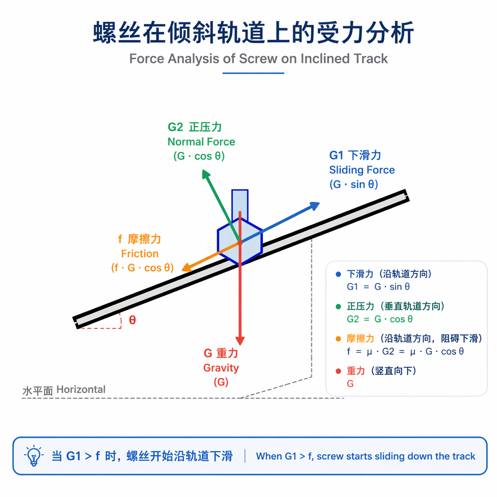
The track inclination angle (angle with the horizontal plane) is the primary parameter affecting screw sliding speed. If the angle is too small, the screw's gravitational component is insufficient, causing it to stagnate on the track; if too large, the sliding speed becomes excessive, leading to impact damage or attitude flipping.

Engineering practice shows that the optimal inclination angle for M2-M4 screws is 3°-5°, for M5-M6 screws is 5°-7°, and for M8 and above can reach 7°-10°. For materials with lower surface friction coefficients such as stainless steel, the angle should be increased by 1°-2°.


II. Track Surface Treatment and Friction Control

Track surface roughness directly affects the friction coefficient between screw and track. Excessively smooth surfaces cause uncontrolled screw sliding, while overly rough surfaces increase friction resistance and reduce feeding speed.

Recommended track surface treatments: stainless steel tracks use brushed finish (Ra 0.8-1.6μm), aluminum alloy tracks use hard anodizing (coating thickness 15-25μm). Key areas can be sprayed with PTFE coating to reduce friction coefficient to 0.05-0.1.

For screws prone to jamming (such as Phillips or Torx heads), guide ribs or limit slots can be added at specific track positions to maintain correct screw orientation.

III. Track Diameter Matching with Screw Specifications

Track diameter (support width for screw head) must precisely match screw head dimensions. If too small, screw head support is insufficient, causing rollover; if too large, screw swing amplitude increases, making attitude unstable.

Design formula: Track diameter D = d + (1.5-2.5)mm, where d is screw head diameter. For example, M4 pan head screws have head diameter of about 7mm, so track diameter should be designed as 8.5-9.5mm.

For countersunk screws, dedicated support steps are required, with step height approximately 1/3-1/2 of screw head thickness, ensuring correct orientation delivery to the separation position.

IV. Balance Between Spiral Rise Angle and Centrifugal Force

During feeder operation, screws on the spiral track simultaneously experience vertical vibration, horizontal centrifugal force, and gravity. Spiral rise angle (angle of track spiral ascent) design must balance these three forces.

Spiral rise angle is typically 1.5°-3°, combined with vibration frequency of 50-100Hz and amplitude of 0.5-2mm. If the angle is too large, screws are easily thrown off track by centrifugal force; if too small, conveying efficiency decreases.

Recommended parameters for different screw specifications:

Screw Size

Track Angle

Spiral Rise

Frequency

Amplitude

M2-M3

3°-4°

1.5°-2°

80-100Hz

0.5-1mm

M4-M5

4°-6°

2°-2.5°

60-80Hz

1-1.5mm

M6-M8

6°-8°

2.5°-3°

50-70Hz

1.5-2mm


V. Track Optimization and Debugging Practice

In actual debugging, a progressive optimization method is recommended: first determine basic track parameters based on screw specifications, then observe screw movement through feeding tests, and finally fine-tune angle and vibration parameters.

Common problem diagnosis: screws slipping on track → increase angle or amplitude; excessive flipping rate → decrease angle or amplitude; screw accumulation jamming → check track smoothness, add baffles if necessary.

Regular maintenance points: inspect track wear every 500 operating hours, clean accumulated oil and metal debris to ensure long-term stable feeding efficiency.

Conclusion

Feeder track design is core technology for automatic screw locking machine feeding systems. Through proper setting of track inclination angle, surface treatment, diameter matching, and spiral rise angle, feeding efficiency can be improved by over 30% while keeping jamming rate below 0.5%. Chisu Automation recommends that equipment manufacturers establish track parameter databases, providing standardized design solutions for different screw specifications, and combine vibratory bowl technology for flexible feeding in special complex scenarios.

Frequently Asked Questions (FAQ)

Q: How often should feeder tracks be replaced?

A: Under normal conditions, stainless steel tracks have a lifespan of about 2-3 years (approximately 5000-8000 hours). When obvious wear grooves appear on the track surface, feeding efficiency drops by more than 20%, or jamming rate exceeds 2%, track replacement is recommended.

Q: Do different screw materials require track adjustments?

A: Yes. Stainless steel screws are lighter and have smoother surfaces than carbon steel screws, typically requiring 1°-2° larger inclination angle. Copper screws are softer and require smoother track surfaces to avoid scratching. Plastic screws need special low-friction tracks and smaller amplitudes.

Q: How to determine if track inclination angle is appropriate?

A: Observe screw movement on track: ideal state is uniform sliding, stable attitude, no flipping. If screws accumulate or slide too slowly, angle is too small; if screws jump or flip, angle is too large. High-speed camera recording can be used for analysis.

Q: What are track surface treatment options?

A: Common treatments include: brushed finish (low cost, good versatility), hard anodizing (aluminum-specific, wear-resistant), PTFE coating (ultra-low friction, suitable for precision screws), ceramic spray coating (ultra wear-resistant, suitable for high-volume production).

Q: Can one Chisu feeder handle multiple screw specifications?

A: The same feeder can usually only accommodate ±1 specification range. For example, a feeder designed for M4 screws can barely handle M3.5 or M4.5 screws, but efficiency and stability will decrease. Important production lines are advised to have dedicated feeders for each screw specification, or use vibratory bowl auxiliary feeding for complex multi-variety scenarios.

— End of Article —

Author: Chisu Automation Technical Department

Published: Week 3, June 2026

Keywords: feeder, track design, feeding efficiency, screw feeding, automatic screw locking machine

← Back to News
📞 Contact
After-sales: 400-876-8800
💬 Pre-sales 🔧 After-sales 📥 Downloads
⬆️ Top